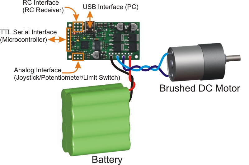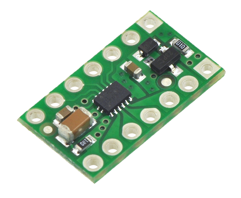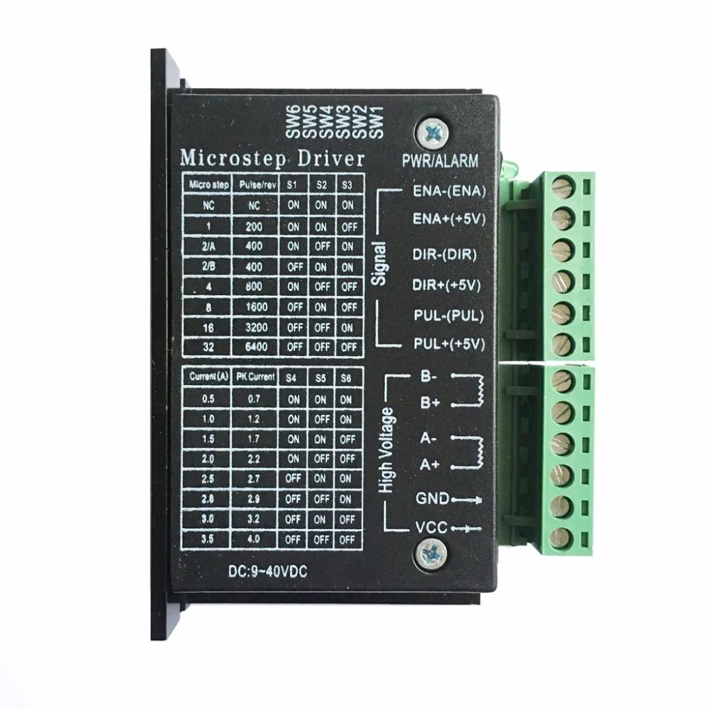
While using the board, please adhere to the following precautions:Īfter operation, allow the board to cool down before touching it. Warning! Some of the components mounted on the board could reach hazardous temperatures during operation. voltagesĭo not put the board in contact with flammable materials of with materials releasing smoke when heated Microstep resolution easily settable through jumpers: full-step, 1/2, 1/4, 1/8, 1/16, 1/32, 1/128 and 1/256 of step Simple step and direction control interfaceĪdjustable current control through a potentiometer to set the ref. Unlike market solutions, the ST820 helps customers truly take advantage of high-microstepping solutions. The hardware is fully compatible for RAMPS or other similar FFF 3D printing platform, representing a quick alternative to similar solutions. A compact solution for stepper motor drives with minimal external equipment, no additional components required.
#Motor driver controller driver#
Here you see that the motor enable pins connect to pin 10 and pin 5, both of which are PWM pins.The ST820 is an easy-to-use driver board for 3D printers, routers and more. However, for motor speed control, the motor enable pins must be attached to a PWM enabled pin. You can attach the control pins to any digital (or even analog) pins. Using the L298N with ArduinoĪn example diagram for connecting the L298N motor controller board to an Arduino is shown: Thus, the actual pulse width must be derived through experiment. How fast the motor rotates for a given pulse width will vary from motor to motor even if they look exactly the same. The wider the pulses, the faster the motor rotates. The speed of the motor will vary according to the width of the pulses. All you need is feed PWM signals to the motor enable pins. Speed control is also possible with the L298N motor driver. These assumes you are following the same Fritzing diagram above. Here’s a table that summarizes the pins and corresponding motor direction. To reverse the direction, reverse the pulses to IN1 and IN2. If you want the left motor to rotate in one direction, apply a high pulse to IN1 and a low pulse to IN2. Here is a wiring diagram for connecting two DC motors to the L298N driver board. Speed control for Motor A and Motor B is achieved via PWM on these pins. Remove these jumpers if you are using DC motors and keep it for stepper motors.

There are also two other jumpers on the board, as shown. Specifically, motor A connects to terminals 1 and 2 while Motor B connects to terminals 3 and 4. The motor terminals connect to Motor Terminals 1, 2, 3, 4. You have Motor A inputs and Motor B inputs. This means the +5V terminal is not for powering the board but for connecting a device, say Arduino, that needs a 5V source. When the +12V jumper is attached, the on-board voltage regulator is now enabled, and you can source +5V from the +5V terminal. Important note: remove the +12V jumper shown if you are using powers higher than +12V.


More information about the L298N IC is found on its datasheet: This means you can power high voltage motors while controlling them with microcontrollers.

The most notable feature here is its high power supply although its input pins follow lower voltage levels. The diagram above shows an example diagram for using the L298N to drive one DC motor. To drive the motor counter clockwise, the pin Input 1 is low while the pin Input 2 is high. To drive a motor to a direction, say, clockwise, the pin Input 1 must be high while the pin Input 2 must be low. The Enable A pin must be high to turn on the motor. For example, if a motor is using channel A, its terminals must be connected to pins Out 1 and Out 2. This IC drives two motors through two channels, A and B. It comes in two IC packages: MultiWatt15 and PowerSO20. The L298N is an integrated circuit that follows the H-bridge concept. This is very significant especially when using an Arduino board where the 5V power source is simply not enough for two DC motors. The other benefit of using an H-bridge is that you can provide a separate power supply to the motors.


 0 kommentar(er)
